

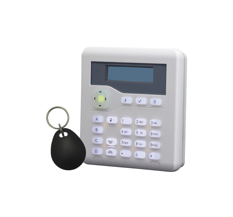
 The i-on Compact Security System is a Grade 2 wired intrusion detection panel with 10 zones and up to 10 users and 4 keypads. It is promoted as being suitable for simple, entry-level burglar alarm systems to protect homes and small commercial installations. This i-on 10-KP version includes an integral proximity reader. The panel size is 239mm (h) x 250mm (w) x 90mm (d) with a weight of 2.8 kg without the battery.
Getting started
The panel has two crosshead screws holding the cover in place. Once this is removed the keypad can be found secured beneath the panel’s circuit board. Once this is removed, a fourth mounting pillar must be fitted to support the PCB. Mains power connection is made using a three-way fused terminal block at the top left of the chassis. On the model tested, the power connection detail was partially obscured by the connector block but is clearly shown in the installation instructions.
Space is available within the chassis for a 12v 7Ah battery (not supplied). This does not power up the system before mains power is supplied but a “Kick-start” link on the PCB can be briefly shorted to configure the system without mains power.
The keypad is connected to the panel via a 4-way connector for 0v, 12v, A & B for its power and serial communication. Up to three additional keypads can be added using either bus or star wiring configurations. Alarm devices are attached to the PCB using a two-wire alarm format plus power from the 12v auxiliary outputs.
A component pack within the housing contains EOL (End Of Line) resistors (10 x 2.2kΩ and 10 x 4.7kΩ), the PCB mounting pillar and screw, 3 x PCB links, keypad cover screws, a wall plug & screw and a cable tie for power lead strain relief. The single screw and wall-plug is for securing the keypad’s tamper block fixing. An optional communicator is available that can be mounted beneath the main PCB.
Menu options
At first power-up the 2 line by 20 character LCD display takes the operator through a series of initial configuration setup options. Firstly, to set the addresses of any keypads connected press the A and Tick buttons together for around three seconds till the keypad bleeps. Next the wired Zone type is entered; the default is for 2-wire FSL (Fully Supervised Loop) 2k2/4k7. Alternative EOL and Alarm resistor values of 1k0/1k0, 2k2/2k2 or 4k7/4k7 can be selected. The next option is for the user code length as either 4 or 6 digits after which the Installer then User codes are entered. The screen will then display the system ident and currently stored Time & Date unless the main panel is still open, where an “Installer Exit Faults” message is then displayed.
Read the full review in the February 2022 edition of PSI magazine here