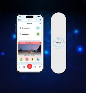
 The Optex Olarm Max is a compact alarm communicator unit supporting 4G, LoRaWAN, and Wi-Fi connectivity. It has dimensions of 200 x 50 x 20 mm and a weight of approximately 140 grammes. With the phase-out of PSTN technology, this device is intended to provide a simple upgrade solution to dual or multi-path alarm system management.
Getting started
For wall mounting, the back cover, which is slid onto the main casing, can be fixed to the wall using the four corner-positioned mounting holes and supplied fixings. The bottom left section has a break-off tab containing the tamper switch actuator. A plastic “plug” is inserted into the lower right of the casing to prevent case separation once installed.
As with all such wireless devices the unit should be mounted away from interference sources and large metallic structures.
The device is supplied with a multicore lead with a 4-way and a 5-way connector on either end. This is intended to be cut to suit the specific alarm panel being used. In the case of a Texecom panel the 5-way connector is used, so the 4-way connector end is cut and the cores dressed for connection into the Olarm Max.
A 3.7v supercapacitor is used for battery backup purposes. This is pre-wired and should be plugged into the two-pole connector accessible once the back cover is removed.
A break-out section is positioned near the top-right of the module for an optional external 4G antennae.
The connections are made using a 12-way block to the right of the unit’s rear. The first two connections are for its 7-24v power and ground, followed by two for serial data. Then two I/O ports, RS232 Tx and Rx with the final four connections being allocated for RS422 / RS485 designated as A, B, Y, & Z. The I/O ports allow for interfacing to additional devices.
Programming
The unit must be linked into the alarm system using the relevant alarm panel’s menu system. Basic information on the process is included for the main alarm units supported, but familiarity with the alarm system’s programming is required.
A clear front light sequence shows the status as the unit links into the system. This begins with a white light while booting up, through flashing green when connecting to the panel, flashing blue when connecting to the cloud and finally constant blue when connected. Various additional colour combinations are used to indicate firmware upgrade and diagnostic states.
An “FN” button close to the connections can be used to activate WPS mode for Wi-Fi linking.
Read the full review in the December 2024 edition of PSi magazine


