


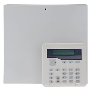
 The i-on G2SM panel and its associated keypad form part of a grade 2 expandable alarm system with the main panel accepting up to 10 zones with expansion capability of up to 50. It includes secure cloud connectivity with app monitoring for customer use and engineering support.
Optional expanders have 10 zones rather than the usual 8 and a 30-zone radio expander can be used. The wired connection bus allows for up to 20 devices such as keypads and expanders. Up to 50 users can be allocated.
Getting started
The steel-cased panel which has dimension of 245 x 239 x 90 mm and a weight of around 2.2 kg without battery, has two captive crosshead screws holding its cover in place. Three fixing points are available for wall-mounting with the top one being open for hooking in place during fixing. A three core mains feed is required to connect into the fuse block at the top of the unit next to the mains transformer. Rear panel access holes allow suitable entry points for all cabling.
The keypad includes a single screw and wall fixing for the tamper breakoff point.
The panel has space for a 12-volt 7Ah battery which may add up to 2.5kg to the total weight. Guidance is given to ensure that the battery capacity supports the system for 12 hours including two 15-minute alarm periods, to meet Grade 2 requirements.
All screw connections are of sensible size accepting standard 3mm terminal drivers. Alarm inputs are at the edge of the pcb and central to the panel so readily accessible for installation. The panel is supplied with a set of 10 x 2.2kΩ and 10 x 4.7 kΩ resistors for alarm and tamper monitoring. These are the default values, but other options including values of 1.0k/1.0k, 2.2k/2.2k or 4.7k/4.7k are possible. The system allows for up to 10 two-wire alarm fully supervised loop inputs but if 4-wire is used the total inputs are halved.
Keypad menu options
At first power-up a startup message such as “Eaton v5.23” appears in the keypad’s LCD display, then after a short delay “Press addr button(s) on wired keypads” appears to show the system has entered configuration mode. You then need to set an address for the keypad by pressing the A and Tick keys together for about three seconds and an address will be allocated, such as “b1-d51” indicating device 51 on bus 1.
There then follow the options for Language, Country Defaults, Partition or Part set mode, System Grade, Wiring Type, Confirmation Mode (if UK selected), Installer code, Remote Password, and User 1 code.
A telephone style numeric keypad allows for alphanumeric characters to be entered, with the # key toggling between upper and lower case.
Read the full test report in the July 2024 edition of PSi magazine