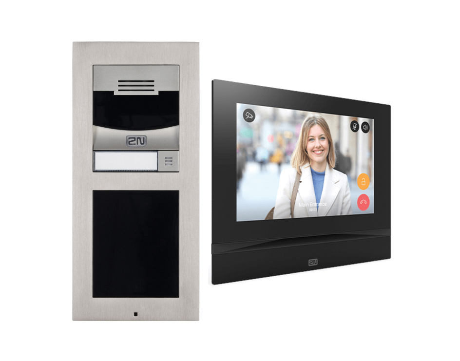
 The door unit is IP54 rated, with IK08 impact rating (IK07 for display). It is produced in modules that can be extended to allow for numeric entry keypads, card readers and button arrays. It supports voice and video communication calls to mobile phones and tablets and can be integrated into security systems.
The camera has a JPEG resolution of 1280 x 960 pixels and video calls are transmitted at 640 x 480. The indoor viewer is a 7” 1024 x 600 pixel touch screen device that can be desk or wall mounted.
The reader module is a 2N Verso Bluetooth and RFID card reader that is compatible with 125kHz, secured 13.56MHz and NFC. So can work with contactless cards and key fobs as well as selected mobile phones. It supports the following 125 kHz and 13.56 MHz cards or other carriers (only the card serial number is read):
125 kHz – EM4xxx
13.56 MHz – ISO14443A (Mifare, DESFire), PicoPass (HID iClass), FeliCa, ST SR(IX)
2N® Mobile Key – HID SE (Seos, iClass SE, Mifare SE)
Lift control can be implemented using optional relay modules to provide selective access control to multi-floor or high-rise buildings. Audio level and video motion detection features are included for integration with compatible security or home automation systems.
Getting Started
The door and internal units are both PoE enabled but can be fed from 12v DC and a standard network connection port. Basic installation instructions are provided with the products, or pictograms on the box show assembly information. You are referred to the 2N website for manuals.
These can be quite comprehensive but not necessarily the easiest way to get started. The installation manual doesn’t get to the Electrical Installation chapter until page 250 of 319. Much of the information relates to the IP addressing and interconnection of the units with a suitable SIP (Session Initiation Protocol) server. An understanding of SIP configuration is assumed in most of the documentation, and this will likely be more familiar to telecoms engineers and may be less so for security system installers. It is possible however, to connect the units as a one-to-one Door to View station link using appropriate network addressing commands but it is certainly not a “plug & play” operation.
A 2N network scanner program can be downloaded to identify the DHCP allocated IP addresses for each of the units. If no DHCP server is available, then a static IP address of 192.168.1.100 can be forced by a timed press of the reset button. This mode is confirmed by an acoustic and LED signal.
Connections within the door unit are provided for Network (RJ45), In 1 (2-pole) for Passive / Active mode, Out 1 (2-pole) for security relay, NO & NC relay contacts (3-pole), 12v in and Ground (3-pole). Alongside the reset switch there are further connectors for the peripherals’ bus, line out and Microphone. The terminals require a narrow terminal driver with a blade of less than 3mm.
The Door station has a changeover relay that can be used to control the door lock; however, this does place the connections on the unsecured side of the door and could be exposed to attack. 2N produce an optional Security Relay module that uses the “Out 1” terminals to provide a secondary confirmation link and can be placed on the secured side of the door.
The optional card reader module plugs into the peripheral expansion bus and is clipped and secured into the lower section of the door unit. Once connected it becomes available as an option in the devices’ menu structure.
Being low-profile, the outdoor unit surface-mounts to an external wall surface using the backplate.
The indoor viewer has terminals for Network (RJ45), 12v in, Doorbell in and Line out. The accessories allow for desk stand mounting or fitting into a suitable wall aperture.
Some of the configuration information is limited, and users are encouraged on the website to “request more information” and take advantage of the on-line training modules.
Read the full review in the April edition of PSI magazine


